// Docs
CNC lathe (beta)
MillPath turns parts on a CNC lathe (beta): you draw or open the top half of the part, MillPath finds the operations, checks the tools against the bar, the chuck and the tailstock, simulates the job in 2D and 3D and writes the program for your controller. X is a diameter and Z0 is the finished face, as on the machine.
Start a lathe job
- Pick Lathe (beta) under the machine button next to the logo (or on the start screen the first time).
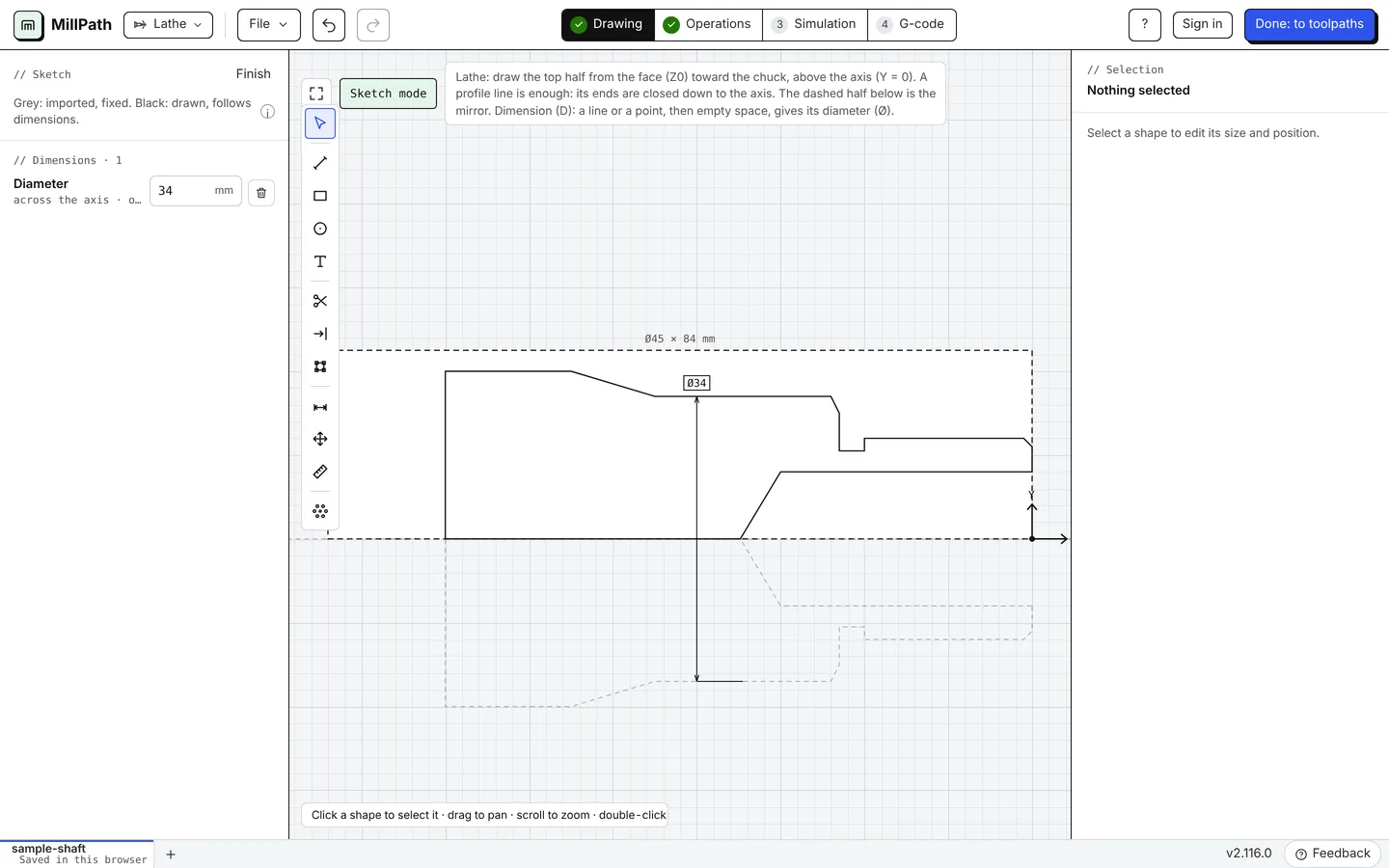
- Open a drawing (DXF, DWG or SVG with the top half of the part), Draw the profile, or Try the sample shaft. A profile line from the face toward the chuck is enough: its ends are closed down to the axis.
- In the drawing, the Dimension tool gives a diameter: click a line of the profile or a point, then empty space, and type the Ø. The line moves and the lines joined to it follow.
The bar, the chuck and the tailstock
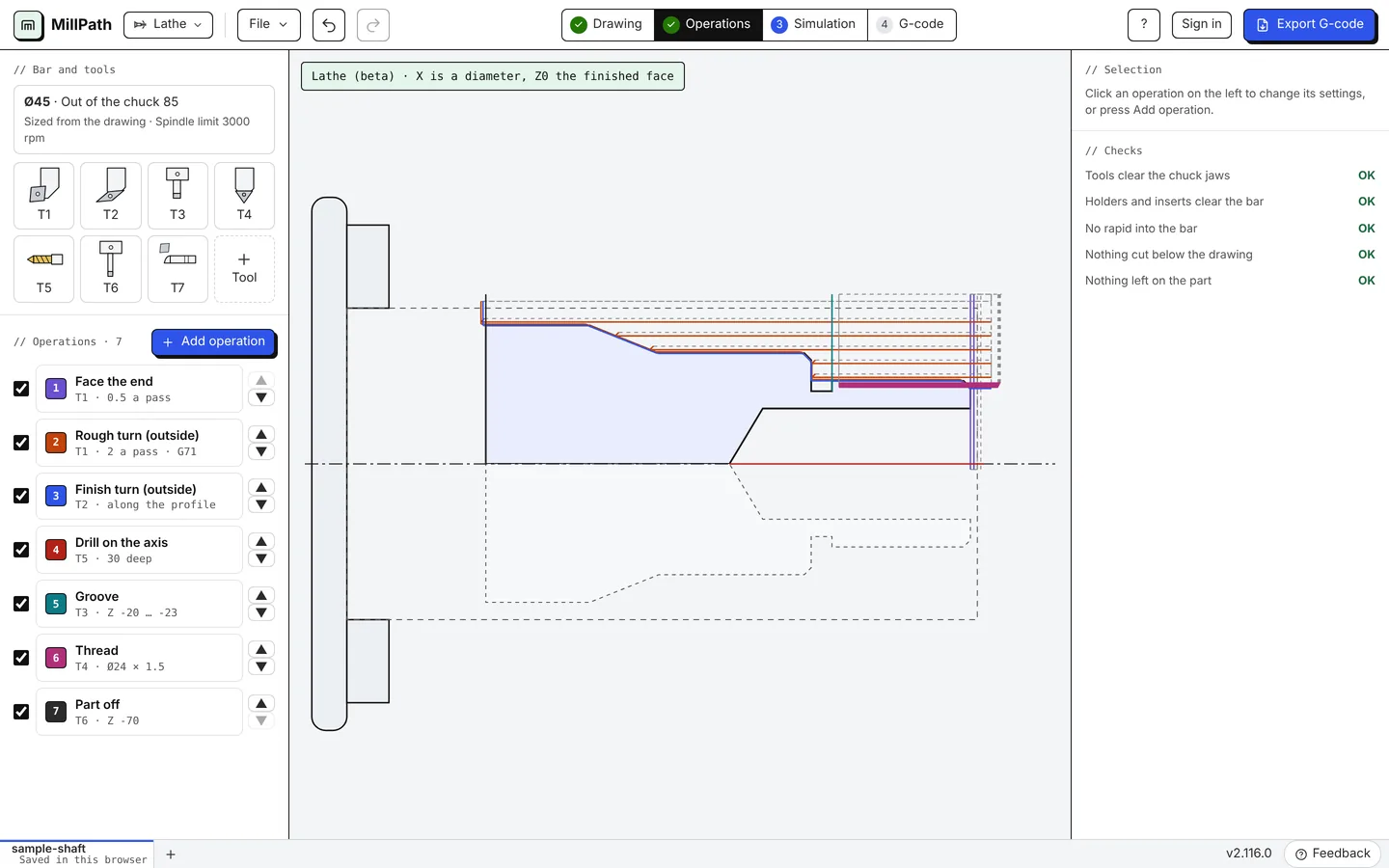
Click the bar line at the top left. The bar is sized from the drawing unless you set it by hand.
- Material: mild steel, stainless, aluminium, brass, cast iron or plastics. Picking one sets the surface speed and feed of every operation to typical starting values for carbide inserts and an HSS-Co drill; check them against the insert box.
- Out of the chuck, stock on the face and bore in the bar (for a tube).
- Chuck: how far the jaws stand above the bar, their length and the chuck diameter. The checks keep tools and holders clear of them.
- Tailstock centre in the face: for long parts. Facing stops short of the centre; drilling and boring need it away.
- Second side: turn the part round. Side 1 parts off a little long, side 2 starts from the part as side 1 leaves it, gripped on its finished side, with its own operations and program.
Operations
Found in the drawing (right) lists what the part needs; Apply all adds them in machining order. Add operation has every kind with a small picture of what it does.
| Operation | What it does |
|---|---|
| Face the end | The end of the bar down to Z0 |
| Rough and finish turn | The outside in passes (G71 / G70 on Fanuc and Haas), then the finish along the profile: one pass, or several closer each time, and a spring pass if you want one |
| Rough and finish bore | The inside, after drilling |
| Back turn and back bore | Undercuts open toward the chuck, cut toward the face |
| Centre drill, drill, tap | On the axis: a 90° spot, peck drilling (G74 / G83), tapping in and out at the pitch |
| Groove and face groove | Undercuts, relief grooves and rings in the face; a groove can have a finish pass that also cuts 45° chamfers at its mouth |
| Thread | Outside or inside, G76 or every pass; 2 or 3 starts; taper threads (NPT, BSPT, 1 in 16) pass by pass |
| Part off | The part off the bar, half feed near the centre; a chamfer drawn on the back edge is cut by the blade’s corner just before it parts |
The nose radius is taken out in the toolpath, so tapers, chamfers and radii come out as drawn; on a finish you can leave it to the controller (G41 / G42) instead. Radii are written as G2 / G3 arcs.
Tools and their real size
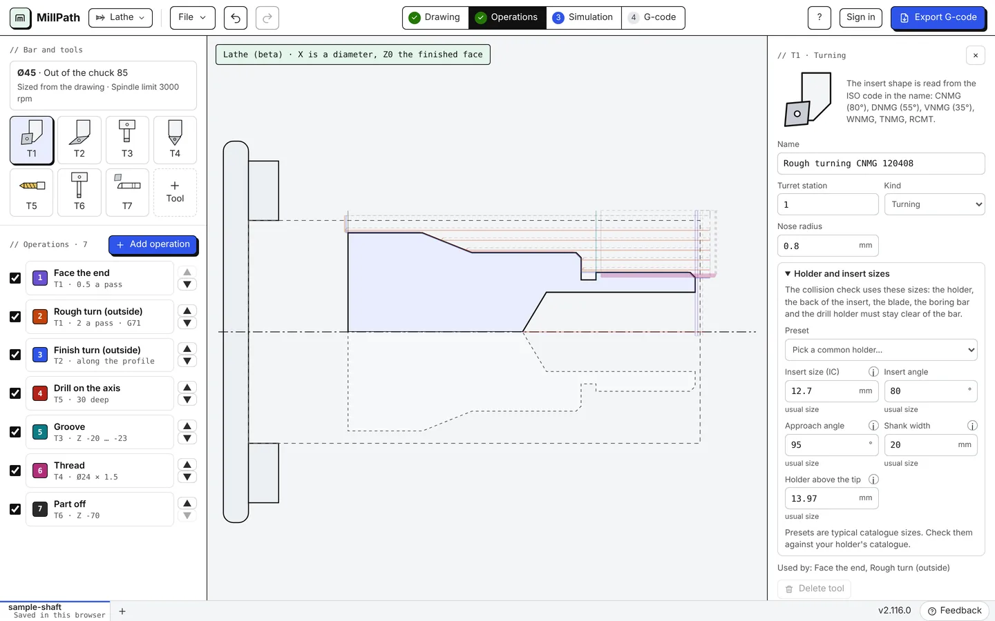
The turret shows each tool as it sits in its holder. Click one to set its insert (the ISO code in the name gives the shape and nose radius), its holder and insert sizes (approach angle, shank, the blade’s deepest cut, the boring bar’s diameter, the drill’s flute length) or pick a common holder. The presets are typical catalogue sizes: check them against your own catalogue.
Checks and simulation
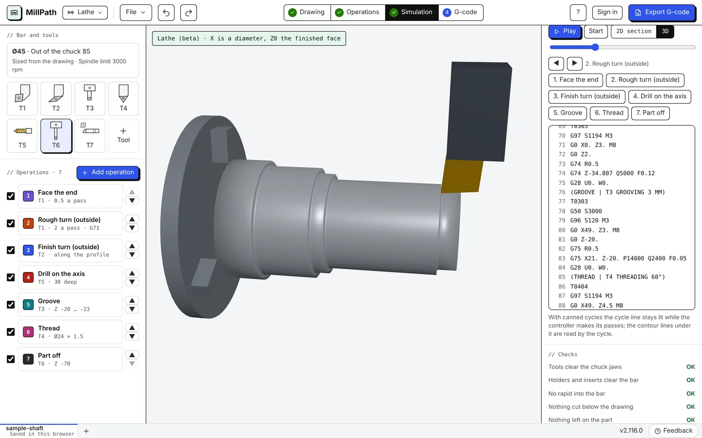
The checks run on every change: tools clear the chuck jaws, holders and inserts clear the bar, no rapid into the bar, nothing cut below the drawing and nothing left on the part. A hit names the tool, where it is and what to change; Show takes the simulation there and a red mark shows the place.
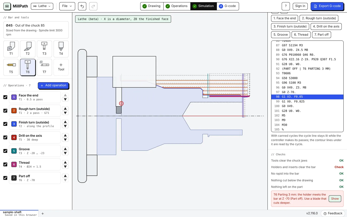
Simulation plays the job in the 2D section or in 3D, with the tool drawn as it is. Step move by move with the arrows; the program line making each move is lit, and a click on a line goes there. The cycle time is an estimate.
The program
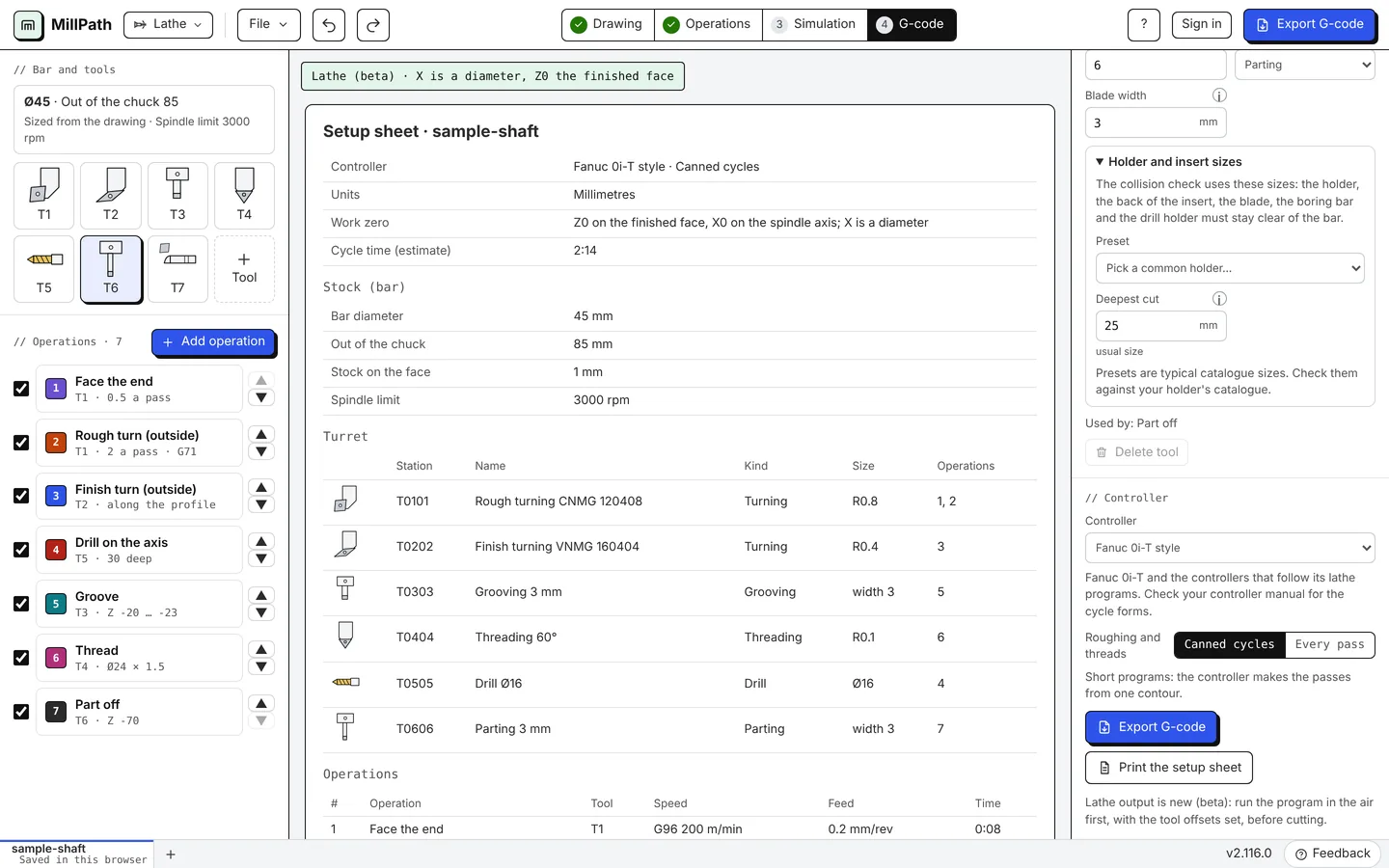
The G-code step shows a setup sheet to print for the machine (bar, work zero, turret, operations with speeds, feeds and times) and the program under it. Pick your controller there:
| Controller | What is written |
|---|---|
| Fanuc 0i-T style | G71 / G70, G76, G74, G75 canned cycles, or every pass; G code system A or B |
| Fanuc 6T / 10T / 15T (beta) | One-block G71 and G76 (D and K with no decimal point), drilling and grooving every pass |
| GSK 980TD / 980TDi (beta) | Fanuc style two-block cycles, the G71 feed on its first block, plain comments |
| Syntec, Mitsubishi M70 / M80 / M800 (beta) | Written as for Fanuc 0i-T; Mitsubishi G code lists 3, 5 and 7 take system B; each is its own choice so run reports count for that control |
| Mazak EIA / ISO (beta) | Standard two-block cycles, G76 P(m r a) R, P and Q with a decimal point |
| Haas lathe | G71 / G70, G76 one block, G83 drilling |
| Okuma OSP (beta) | LAP roughing G85 / G87 with the contour between G81 and G80 (D and U on the diameter), arcs with L, no G20 / G21 or G28; threads written out |
| Fagor 8055T / 8037T (beta) | G71 / G70 for units, G95, G151, G92 S, T and D, G33 with L, every pass |
| grblHAL lathe mode (beta) | G7, G95, a fixed rpm, G33 with K, every pass |
| LinuxCNC lathe | Diameter mode G7, every pass, G33 threads, G33.1 tapping |
| Siemens Sinumerik (beta) | DIAMON, G96 with LIMS, arcs with CR=, every pass |
| Mach3 / Mach4 Turn (beta) | Fanuc style words, every pass, a fixed rpm |
The badge beside the controller shows how many MillPath users have run that lathe post fine. After a run, Report how a program ran (under the export button) tells us how it went: see Reports.
Learn it
Two short lessons open the sample shaft and show where to click: Your first turned part and Tool sizes and collisions. Open them from the start screen (“Learn MillPath”) or the ? menu.